How To Maintain The Mixing Head Of A PUF Sandwich Panel Production Line
Oct 13, 2026
The mixing head is the heart of any polyurethane foam sandwich panel line, and its condition directly determines panel consistency, bond strength, and output rate. This guide walks through practical maintenance habits that extend head life, reduce downtime, and keep foam quality stable shift after shift.
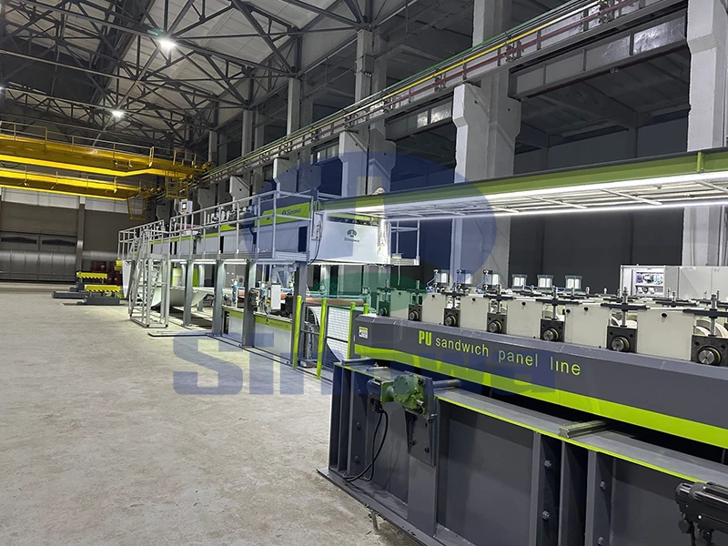
The mixing head sits at the point where polyol blend and isocyanate streams collide under high pressure before being sprayed onto the facing material. Inside, two opposed pistons or nozzle tips strike each other with controlled force, breaking the liquid streams into microscopic droplets that then combine and react. Because the chemistry is fast and exothermic, any deviation in timing, pressure, or stream alignment shows up immediately as uneven density, skin defects, delamination, or scorched spots. Routine maintenance is therefore not an optional extra but the primary control over product quality. Operators should treat the head as a precision instrument rather than a simple pipe junction; the clearance between moving parts is measured in tenths of a millimeter, and even small deposits of cured foam or worn seal surfaces can shift the mixing energy enough to ruin a batch. Before starting any maintenance task, make sure the line is locked out, the hydraulic or pneumatic supply is depressurized, and the chemical lines are isolated. Residual isocyanate and polyol can cause burns or sensitization, so wear the gloves, eye protection, and respiratory mask specified for the chemistry on site.
The most frequent task is end-of-shift cleaning. When the line stops, residual material inside the chamber will begin to react almost immediately and, if left overnight, will harden into a solid plug that can only be removed by disassembly and mechanical scraping. The standard practice is to run a solvent flush through the mixing chamber using the head's built-in cleaning circuit immediately after the last pour. Most heads use either a flushing piston that pushes solvent through the chamber or a separate solvent injection port. The flush should continue until the discharged solvent runs clear and free of cloudy streaks, which indicates that both stream paths have been purged. It is tempting to cut this step short at the end of a long shift, but a rushed flush is the single most common cause of morning failures. After the flush, leave the head open or park the cleaning piston in its fully forward position so that air can circulate and any remaining solvent evaporates rather than sitting in a pocket where it can degrade seals over time. Record the flush time and solvent batch in the shift log, because changes in how quickly the solvent runs clear can be an early warning of a partially blocked nozzle.
Material residue can still form in hard-to-reach areas such as the corners of the mixing chamber, the gap behind the impeller or piston, and the annular space around the stream-switching valve. These deposits build up gradually, and at first they only subtly alter the angle at which the two streams meet. Over a few weeks the deposit can redirect one stream so that it hits the chamber wall instead of the opposing stream, producing a weak mix and a visible stripe of unreacted material on the panel. To prevent this, perform a partial tear-down every few runs as defined by the line's duty cycle. Remove the chamber block, inspect the internal surfaces with a flashlight, and use a soft brass or plastic scraper to lift any crust that has formed. Never use a steel blade on the mating surfaces, because a scratch will act as a nucleation point for future deposits and will also trap small seal fragments. After scraping, wipe the surfaces with a lint-free cloth soaked in solvent and run a test pour onto scrap facing material to confirm that the stream pattern is symmetric. A clean head should produce a cone-shaped spray with even edge definition; any lobe, wobble, or asymmetry means the cleaning was incomplete.
Seals and O-rings are the components most often overlooked until they leak. The mixing head contains seals for the chemical inlet valves, the high-pressure circulation piston, and often the hydraulic actuator that drives the cleaning piston. Each seal sits in a harsh environment: chemical contact, solvent exposure, and repeated thermal cycling. A small leak around a seal may seem harmless, but it allows isocyanate to creep along the seal face and react with atmospheric moisture, forming a solid crust that damages the seal seat and accelerates wear. During every shift, walk around the head and visually inspect every sealing point for dampness, crystal formation, or discolored stains on the mounting bolts. Squeeze the drain ports at the bottom of the seal cartridge to see whether any chemical has collected there; a wet drain is a definitive sign that the primary seal has failed. When replacing a seal, always lubricate it with the fluid specified in the seal manufacturer's guidance—usually a light silicone oil for chemical-service seals—and never force it into the groove with a sharp tool. A twisted or nicked O-ring will fail within hours, and the replacement will be wasted effort.
Nozzle tips and the seat against which they strike are the precision core of the head. Over time, the repeated impact of two high-pressure streams erodes the tip edges, turning a sharp, square-edged orifice into a rounded one. A rounded orifice produces a wider, less energetic stream, which lowers the mixing index and leads to larger cell size in the foam. Inspect the tip interiors during the weekly tear-down by unscrewing each nozzle and holding it up to a light. A healthy tip has a smooth, glossy bore with no pitting, scoring, or visible wear on the inlet chamfer. If the bore looks cloudy or grooved, replace the tip rather than trying to hone it, because honing changes the orifice diameter and therefore the flow rate. Also check the strike face—the surface against which the streams impinge—for cratering. A shallow crater is normal wear, but a deep crater indicates that the impact pressure has been set too high or that the tips are misaligned. Record the number of runs on each tip, because tip life is predictable once you have a few months of data; replacing tips before they fail is far cheaper than scraping a half-finished shift because of a sudden quality collapse.
The solvent used for flushing and cleaning matters more than many operators realize. A solvent that evaporates too quickly can leave resinous residues behind as it flashes off, while one that is too aggressive can swell certain seal materials and shorten their life. The best practice is to use a solvent that is chemically compatible with both the isocyanate and the polyol in use, and to change the solvent in the flush reservoir on a fixed schedule rather than using it until it looks dirty. Contaminated solvent is a common hidden cause of slow cleaning: when the solvent has already dissolved its capacity of resin, it no longer has the capacity to lift fresh deposits, and the operator ends up flushing for longer without improving the result. Keep the solvent reservoir covered to prevent moisture pickup, because isocyanate reacts with water and can form insoluble solids in the flush circuit. When wiping down exterior surfaces, use a separate cloth from the one used inside the chamber, because exterior cleaning often picks up dust and facing-fiber debris that should not be introduced into precision bores. Dispose of used solvent and contaminated cloths according to local waste rules, and never pour solvent back into the fresh container.
Wear parts have predictable lifetimes, and keeping spares on hand avoids panic substitutions at the end of a run. The typical wear kit for a mixing head includes nozzle tips, stream-switching seals, cleaning-piston O-rings, chamber gaskets, and the small springs that seat the check valves. Store these parts in their original sealed packaging until needed, because exposure to airborne dust can contaminate a bore even before installation. When installing a new part, compare it against the old one under magnification to confirm that the dimensions, especially the orifice diameter and seal cross-section, match the drawing. Substituting a tip with a slightly different bore size changes the flow balance between the two components, which shifts the index ratio and can produce either under-indexed foam that is too soft or over-indexed foam that is brittle. If a substitute is unavoidable, record the change and run a density test on the first panel after the swap, adjusting the pour weight until the target is restored. Keep a small log next to the head showing the installation date of every consumable part; this turns maintenance from guesswork into a schedule and prevents the common problem of forgetting which seal was replaced last week.
Operators themselves are the most important maintenance system, because most problems are detected by feel, sound, and sight long before they appear on gauges. A healthy mixing head has a steady, rhythmic beat as the streams strike; a change in pitch, a rattle, or a new vibration usually means a tip is loose, a seal is failing, or a deposit has built up inside. Encourage operators to report any small anomaly immediately rather than waiting for it to become a visible defect. Train them to recognize the visual signs: a change in the color of the discharged foam, streaks of white or clear material, a shift in the spray pattern, or a drop in pressure on the stream gauges. Cross-train at least two people on every line so that maintenance knowledge is not locked in a single operator's head, and schedule a short weekly review where the team looks at the wear parts removed in the last tear-down and discusses whether any part is wearing faster than expected. This review often surfaces subtle issues—contaminated raw material, misaligned facing material, or slightly off pump pressure—before they become expensive failures. Good maintenance is ultimately a culture of small, consistent actions rather than a list of big interventions, and the operators who live with the head every day are the best people to judge when something is quietly wrong.
Gallery
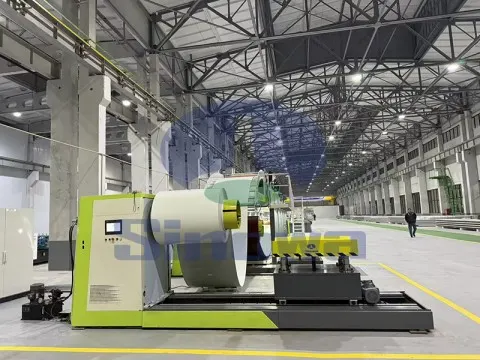
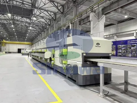
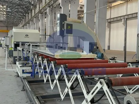
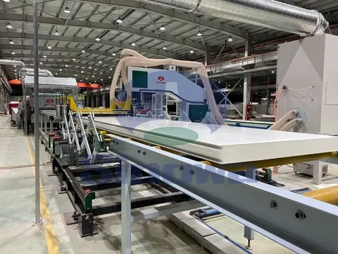
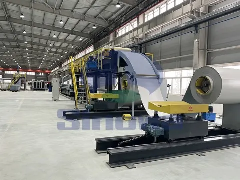
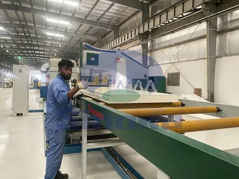
Sinowa is a professional manufacturer of sandwich panel machine in china, we provide diversified and high-performance sandwich panel production lines, including fully automatic continuous PU sandwich panel line and customized special lines to meet mass production and personalized order demands. These sandwich panel lines support processing multiple foam core materials, such as PU, PIR, mineral wool, rock wool and glass wool, covering different insulation and fireproof standards.
Featuring stable operation, high efficiency, energy saving and easy maintenance, our PU sandwich panel line deliver sandwich panels with excellent thermal insulation, fire resistance, sound insulation and lightweight durability. The finished panels are widely applied in industrial workshops, warehouse roofing and wall cladding, cold storage insulation, serving global construction and industrial insulation markets.
Main Products
-

Continuous PU Sandwich Panel Production Line
This continuous PU sandwich panel production line is an integrated automatic equipment. It covers uncoiling, forming, foaming, curing and cutting processes. With automatic raw material proportioning and precise temperature & pressure control, PIR sandwich panel production line continuously composites panels with double skins. Polyurethane sandwich panel production line stably produces steel and aluminum sandwich panels. Featuring high automation, the line makes fireproof and thermal-insulation panels for building enclosure and cold storage. -
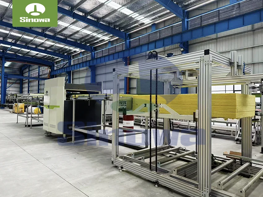
Rock Wool Sandwich Panel Production Line
Continuous rockwool sandwich panel production line is an automatic integrated production equipment, consisting of uncoiling, forming, gluing and compounding, heating curing, fixed-length cutting, automatic stacking and other modules. The mineral wool sandwich panel production line continuously conveys color steel plates and rock wool core materials to automatically complete lamination and curing, which can produce fireproof and thermal insulation sandwich panels. Featuring high automation degree and stable operation, this production line is suitable for mass production of panels used for building walls, roofs and other scenarios. -
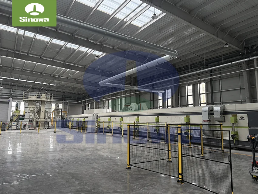
Phenolic Insulation Board Production Line
This integrated automatic production line continuously manufactures PU and phenolic insulation boards. The insulation board production line covers raw material proportioning, high-pressure foaming, laminating, curing and fixed-length cutting. Featuring high automation and stable molding, the insulation panel production line supports various surface materials. PU boards offer excellent thermal insulation, while phenolic boards have superior fire resistance. These products are widely used in construction, cold chain, ventilation ducts and other thermal insulation fields.
Other FAQs
- What Temperature Range Is Suitable For Continuous PU Sandwich Panel Production Line Operation
- What Cooling System Is Required For A Continuous PU Sandwich Panel Line
- Can A Polyurethane Sandwich Panel Production Line Produce Pir Sandwich Panels
- What Are The Common Faults Of A Polyurethane Sandwich Panel Machine
- How To Optimize Cutting Sequence Of PIR Sandwich Panel Production Line Batch Panels
- How To Adjust The Feeding Speed Of Insulation Panel Production Line For Stable Output
- Can A Continuous PU Sandwich Panel Production Line Be Customized For Special Panel Profiles
- Why Does The PUR Sandwich Panel Production Line Have Inaccurate Cutting Length
- Working Principle of PU Sandwich Panel Production Line
- PU Sandwich Panel Production Line Vibration Reduction And Noise Control Scheme
Related Articles
- High-tech PU Sandwich Panel Line Manufacturer
- PIR Sandwich Panel Production Line For Sale With Installation Service
- PIR Sandwich Panel Line For Roof and Wall
- PU Sandwich Panel Manufacturing Machine For Glass Wool Composite Panels
- Principle of Color Steel PU Sandwich Panel Machine
- PU Sandwich Panel Manufacturing Line For Fire-Resistant Wall
- PIR Sandwich Panel Production Line For Acoustic Insulation Panels
- PIR Sandwich Panel Machinery
- Polyurethane Sandwich Panel Line For Prefabricated House Panels
- Composite PU Sandwich Panel Line